Rectangular waveguides
are th one of the earliest type of the transmission lines. They are used
in many applications. A lot of components such as isolators, detectors,
attenuators, couplers and slotted lines are available for various standard
waveguide bands between 1 GHz to above 220 GHz.
A rectangular waveguide
supports TM and TE modes but not TEM waves because we cannot define a
unique voltage since there is only one conductor in a rectangular waveguide.
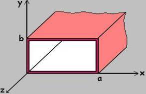
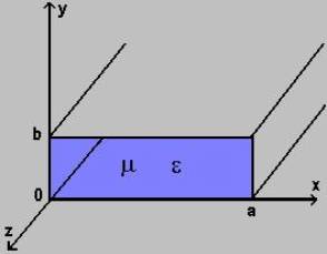
The shape of a rectangular waveguide is as shown below. A material with
permittivity e and permeability m fills the inside of the conductor.
 A
rectangular waveguide cannot propagate below some certain frequency. This
frequency is called the cut-off frequency.
A
rectangular waveguide cannot propagate below some certain frequency. This
frequency is called the cut-off frequency.
Here, we will discuss
TM mode rectangular waveguides and TE mode rectangular waveguides separately.
Let�s start with the TM mode.
TM
Modes
Consider the shape
of the rectangular waveguide above with dimensions a and b (assume a>b)
and the parameters e and m. For TM waves Hz
= 0 and Ez should be solved from equation for TM mode;
Ñ2xy
Ez0 + h2 Ez0 =
0
Since Ez(x,y,z)
= Ez0(x,y)e-gz, we get the following
equation,
If we use the method
of separation of variables, that is Ez0(x,y)=X(x).Y(y)
we get,

Since the right side
contains x terms only and the left side contains y terms only, they are
both equal to a constant. Calling that constant as kx2,
we get;

where ky2=h2-kx2
Now, we should solve
for X and Y from the preceding equations. Also we have the boundary conditions
of;
Ez0(0,y)=0
Ez0(a,y)=0
Ez0(x,0)=0
Ez0(x,b)=0
From all these, we
conclude that
X(x) is in the form
of sin kxx, where kx=mp/a, m=1,2,3,�
Y(y) is in the form
of sin kyy, where ky=np/b, n=1,2,3,�
So the solution for
Ez0(x,y) is
 (V/m)
(V/m)
From ky2=h2-kx2,
we have;

For TM waves, we
have
From these equations,
we get
- where

Here, m and n represent
possible modes and it is designated as the TMmn mode. m denotes
the number of half cycle variations of the fields in the x-direction and
n denotes the number of half cycle variations of the fields in the y-direction.
When we observe the
above equations we see that for TM modes in rectangular waveguides,
neither m nor n can be zero. This is because of the fact that
the field expressions are identically zero if either m or n is zero. Therefore,
the lowest mode for rectangular waveguide TM mode is TM11 .
Here, the cut-off
wave number is

and therefore,

The cut-off frequency
is at the point where g vanishes. Therefore,
Since l=u/f,
we have the cut-off wavelength,
At a given operating
frequency f, only those frequencies, which have fc<f will
propagate. The modes with f<fc will lead to an imaginary
b which means that the field components will decay exponentially
and will not propagate. Such modes are called cut-off or evanescent
modes.
The mode with the
lowest cut-off frequency is called the dominant mode. Since TM
modes for rectangular waveguides start from TM11 mode, the
dominant frequency is
The wave impedance
is defined as the ratio of the transverse electric and magnetic fields.
Therefore, we get from the expressions for Ex and Hy
(see the equations above);

The guide wavelength
is defined as the distance between two equal phase planes along the waveguide
and it is equal to


which is thus greater
than l, the wavelength of a plane wave in the filling medium.
The phase velocity
is


which is greater
than the speed of light (plane wave) in the filling material.
Attenuation for propagating
modes results when there are losses in the dielectric and in the imperfectly
conducting guide walls. The attenuation constant due to the losses in
the dielectric can be found as follows:

TE
Modes
Consider again the
rectangular waveguide below with dimensions a and b (assume a>b) and
the parameters e and m.
 For
TE waves Ez = 0 and Hz should be solved from
equation for TE mode;
For
TE waves Ez = 0 and Hz should be solved from
equation for TE mode;
Ñ2xy
Hz + h2 Hz = 0
Since Hz(x,y,z)
= Hz0(x,y)e-gz, we get the following
equation,
If we use the method
of separation of variables, that is Hz0(x,y)=X(x).Y(y)
we get,
Since the right side
contains x terms only and the left side contains y terms only, they are
both equal to a constant. Calling that constant as kx2,
we get;

where ky2=h2-kx2
Here, we must solve
for X and Y from the preceding equations. Also we have the following boundary
conditions:
 at
x=0
at
x=0
 at
x=a
at
x=a
 at
y=0
at
y=0
 at
y=b
at
y=b
From all these, we get
 (A/m)
(A/m)
From ky2=h2-kx2,
we have;
For TE waves, we
have
From these equations,
we obtain
where
As explained before,
m and n represent possible modes and it is shown as the TEmn
mode. m denotes the number of half cycle variations of the fields in the
x-direction and n denotes the number of half cycle variations of the fields
in the y-direction.
Here, the cut-off
wave number is
and therefore,

The cut-off frequency
is at the point where g vanishes. Therefore,
Since l=u/f,
we have the cut-off wavelength,

At a given operating
frequency f, only those frequencies, which have f>fc will
propagate. The modes with f<fc will not propagate.
The mode with the
lowest cut-off frequency is called the dominant mode. Since TE10
mode is the minimum possible mode that gives nonzero field expressions
for rectangular waveguides, it is the dominant mode of a rectangular waveguide
with a>b and so the dominant frequency is
The wave impedance
is defined as the ratio of the transverse electric and magnetic fields.
Therefore, we get from the expressions for Ex and Hy
(see the equations above);

The guide wavelength
is defined as the distance between two equal phase planes along the waveguide
and it is equal to


which is thus greater
than l, the wavelength of a plane wave in the filling medium.
The phase velocity
is


which is greater
than the speed of the plane wave in the filling material.
The attenuation constant
due to the losses in the dielectric is obtained as follows:
After some manipulation,
we get
Example:
Consier a length
of air-filled copper X-band waveguide, with dimensions a=2.286cm, b=1.016cm.
Find the cut-off frequencies of the first four propagating modes.
Solution:
From the formula
for the cut-off frequency