Bilkent University
Department of Electrical and Electronics Engineering
EEE 212: Microprocessors - 2008 Spring Semester
HOW TO TEST AND PROGRAM THE 8051 TRAINER BOARD
(The reference : http://www.microdigitaled.com/hardware/mde8051/test_prog/Testing%20&%20Programming.htm)
-Purpose:
The purpose of using Hyperterminal with MDE8051 is loading .HEX files into the microcontroller. HEX files are the outputs of compiled firmwares and used for running your programs on embedded systems.
-Testing the 8051 Trainer Board :
a) Connect the Serial 0 of the 8051
Trainer to COM port of the PC using DB-9 cable.
b) On your PC go to Start , Accessories, Communications, select
HyperTerminal.
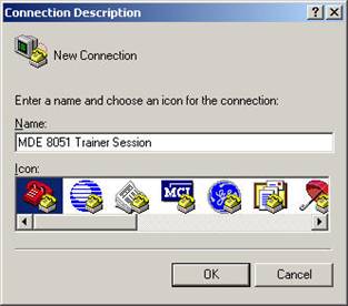
c) Enter a name for the terminal session.
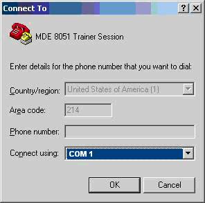
d) Select the PC COM Port the MDE 8051 is connected to. Use COM 1.
e) Configure
HyperTerminal for the following settings.
9600 8n1 with no hardware flow control
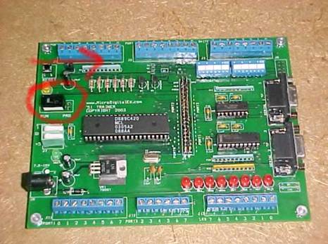
f) Connect the power
g) Put the Switch on PRG Like Shown
h) Go to your terminal
emulator i.e. Hyper Terminal and press Enter.
You should now see the following message on the screen.
DS89C420 LOADER
VERSION 1.0 COPYRIGHT (C) 2000 DALLAS SEMICONDUCTOR
>
You are now ready to load a HEX file into the trainer.
-How To Load
and Run Programs on 8051 Trainer :
a.) Clear the ROM by entering the following.
>K
b.) Ready the board to load with the following.
>L
c.) Using hyperterminal send a text file to the trainer.
d.) When the dialogue appears select all files and navigate to your HEX file to be sent to the trainer.
e.) You should see a series of G's if you see anything but a G an error has occurred during the load and you should repeat from step a.
f.) If the load was successful you should see a series of G. After this step, switch the boards mode from PRG to RUN and investigate the execution of the loaded .HEX file on the board.
APPENDIX A
-Commands and Errors of the Bootloader-
Command Summaries:
B
Return the CRC-16 (cyclic
redundancy check) of the internal ROM code. This self-CRC computation should
always return 0000h.
C [begin-address
[end-address]]
Return the CRC-16 (cyclic redundancy check) of the flash memory. This
computation is performed over the range unless optional
start and end addresses are given. The CRC-16 algorithm is commonly used in data
communications.
CX [begin-address
[end-address]]
Return the CRC-16 (cyclic redundancy check) of the external RAM. This
computation is performed over the range unless optional
start and end addresses are given. The CRC-16 algorithm is commonly used in data
communications.
D [begin-address
[end-address]]
Dump flash memory in Intel hex format. An optional address range may be
specified. Each record contains up to 32 data bytes.
The last line printed is the end-of-data record.
DX [begin-address [end-address]]
Dump external memory in Intel hex format. This command functions in the same
manner as the D command with the exception
of the target memory being external.
K
Perform an erasure of the
entire flash memory range, including security block, option control register,
and bank-select bit.
L
Load standard ASCII Intel hex
formatted data into flash memory. No lock bits may be set when attempting to
load the internal flash
program memory. Only record types 00 and 01 are processed. Each record of the file
is treated the same way. All characters are
discarded before the header character <:> is read. The rest of the
record, defined by the length byte, is then processed. All characters
following the record checksum and prior to the next <:> are discarded.
Control returns to the command prompt after an
Intel end record is encountered. Prior to programming each byte, the loader
performs a preread of that flash memory location to
assess whether the new hex value can be written. After programming each byte,
the loader reads the flash memory location again
to verify proper programming. The processing of each record is confirmed by an
ACK/NAK response. New records should not be
transmitted until the ACK/NAK byte associated with the previous record has been
received.
The ACK/NAK responses are as follows:
|
G |
good record (Only this response should appear if the code is loaded successfully) |
|
A |
hex record received, which
contains an address not programmable by the L |
|
F |
flash write error |
|
H |
hex record received contained a nonhex character |
|
L |
record length > 20 bytes (type 0); record length > 0 bytes (type 1 EOF) |
|
P |
programming error—loader detected an attempt to write 1’s to 0’s |
|
R |
hex record contained a record
type not supported by the DS89C420 loader |
|
S |
hex record contained an
incorrect checksum |
|
V |
data read back does not match data that was written |
LB
Load blind of internal flash
memory—Loads standard Intel hex-formatted data into internal flash memory. This
command functions
in the same manner as the L command, except that the preprogramming assessment
and postprogramming verification of the
flash memory are not executed by the loader. When using this command, the P and
V NAK responses are not returned by the
loader. All other ACK/NAK responses are still generated by the loader.
LE
Load encryption vector—Loads
standard Intel hex-formatted data into flash security block. This command
functions in the same
manner as the L command, except that it operates on the flash security block
(0–3Fh).
LX
Load external memory—Loads
standard Intel hex-formatted data into external memory. This command functions
similar to the L
command, except that it operates on the external memory (0–FFFFh) and can write
without restriction to any address location in
the range. If an external page mode or MOVX stretch cycle different from the
default setting is desired, the ACON or CKCON registers
should be modified prior to execution of the LX command.
R
Read—Displays the values of
the lock bits, option control register, address control register, clock control
register, power management
register, Ports 0, 1, 2, 3, and the flash control register in the following
format:
LB:XX OCR:XX ACON:XX CKCON:XX PMR:XX P0:XX P1:XX P2:XX P3:XX FCNTL:XX
V
Verify current contents of
flash memory vs. the received Intel hex. This command operates similar to the
load command, except
that it does not write to the flash memory; it compares the data byte(s) in the
flash memory to the byte(s) in the data stream. The
same ACK/NAK response scheme is used during verify operations as is used for
load operations.
VE
Verify encryption
vector—Verifies current contents of the flash security block vs. the received
Intel hex. This command works in the
same manner as the V command, but operates on the flash security block (0–3Fh).
VX
Verify external
memory—Verifies current contents of external memory versus the received Intel
hex. This command works in the
same manner as the ‘V’ command, but operates on external memory (0–FFFFh).
W [LB | OCR | ACON | CKCON | PMR | P0 | P1
| P2 | P3] byte
Writes byte to the requested register. Valid entries for LB are 1 (enable LB1),
3 (enable LB1, LB2), and 7 (enable LB1, LB2, LB3).
ACON register writes modify only bits 7, 6, 5. CKCON register writes modify
only bits 2,1, 0. PMR register writes modify only bit 0.
P3 register writes modify only P3.7–P3.2 (P3.1 and P3.0 are not altered).
^C (<CTRL>+C)
Interrupt whatever is going on, clear all the buffers, put up a prompt, and
wait for the next command. Anything in the type-ahead
buffer is removed. All output is stopped.
ERROR MESSAGES :
E:ARGREQ
An argument or arguments are
required for this command.
E:BADCMD
An invalid command letter was
entered.
E:BADREG
This message is printed if a
register other than OCR, ACON, CKCON, PMR, P0, P1, P2, or P3 is used as the
argument for the W command.
E:BADVAL
The requested value cannot be
programmed into the OCR register because it contains 1’s in bit position(s)
where 0’s have already
been programmed.
E:EXTARG
Extra data was encountered on
the command line when it was not needed. Reenter the command.
E:ILLOPT
The optional parameters given
were in error. If the start address is greater than the end address, either
implicitly or explicitly, then an
error is printed. The range bit implicitly determines the maximum range.
E:LOCK BITS
ENABLED
The requested operation
cannot be performed due to the current lock bit settings.
E:LOCK BITS
ALREADY SET
The requested lock bit
setting cannot be programmed because a higher order lock bit has already been
programmed.
E:NOTHEX
A nonhexadecimal character
was found when expecting a hexadecimal character.
E:VALUE MUST BE
1, 3 OR 7
A value other than 1, 3, or 7 was entered when trying to write the lock bits.
BACK TO THE LABORATORY HOMEPAGE