Ring
Hybrid > Design&[S] parameters at center frequency:
If you know little about the
subject reading some theory might be very helpful before starting to design
or analysis. Therefore, just click the Theory button in the menu
to learn about the subject.
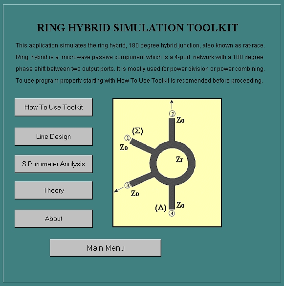
In the Ring Hybrid junction
you will see the following
You can still access to this page from this menu by clicking the How to Use Toolkit button as you see above. Besides throughout the program you will see buttons labeled as Help on some pages. Those buttons are also for this page. Whenever you click that buttons you will see this page.
If you have changed your mind about the type of hybrid junction you want to simulate you can use Main Menu button in this menu to go to back.
Line Design button at the second row will take you to the ring hybrid design page. You can design your ring hybrid in microstrip form or stripline form. You can specify your decision about the type of line for the ring hybrid by clicking one of the radio buttons labeled Microstrip and Stripline as you see below. Whenever you click one of them you will see the related image describing the geometry of the transmission line you selected.

After the specification of the type of line you must enter the dielectric constant (or relative permittivitiy) of the dielectric substrate. If you do not enter anything here you will not start anything on the design page. Other fields will wait until you enter a number into this this dielecetric constant textfield (see the image below). If you do not enter a valid number here you will see a warning message to correct you about the valid number range (valid numbers are ones greater than zero).

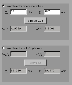
After you enter a valid number in dielectric textfield you will have two options regarding the design of the ring hybrid. You might find the corresponding width over depth ratios(Wo/d and Wr/d) of the ring and feedlines from impedance values (Zo and Zr) of those components or vice versa. You will see a picture describing the ring hybrid and explaining what those variables stand for on that page. If you have impedance values in hand click on the radiobutton labeled as I want to enter impedance values and then write them into corresponding texfields (see the image below). Zo for the feedlines and Zr for the ring. Execute W/d button will stay disabled until you fill both textfield. After you enter your impedance values into textfields just click the button to see the resulting width over depth ratios. The width over depth ratio for feedlines will appear in the textfield labeled as Wo/d and Wr/d textfield for the ring. For example if your feedline width/depth ratio is happened to be 4.9159 (as in following picture) and depth of your dielectric substrate is 4 mm then in order have a 50 ohm feedline you must use a transmission line of width 4.9159x4=19.6636 mm. Or, let's say, you have width and depth information in hand regarding feedlines of your ring hybrid. Then you should first click on I want to enter width/depht ratios radiobutton from the panel. Enter the values in hand to corresponding textfileds. You can enter your width over depth ratio value into the textfield labeled as Wo/d and Wr/d textfield for the ring's width over depth ratio. This time Execute Z button will stay disabled until you enter both of them. Then click on execute button and you will find your corresponding impedance values in ohm. If you have a feedline of width 8 mm and depth 4 mm resulting a width over depth ratio of 2 then after clicking on execute button you might see a impedance value for feedlines like 89.38 ohm.

After impedance and width over depth ratio calculation stuff you might obtain scattering parameters, at center frequency, of current design and also the radius of the ring hybrid, r, on the same page. The panel prepared for this job is below. Here the thing you should do here to obtain S parameters (@ center frequency, fo) and the radius is just enter the deisgn frequency, also regarded as center frequency into textfield you see there. The button on that panel is labeled as Execute [S]ij & r and it will stay disabled until you enter a number in frequncy textfield. The s parameters displayed here will be complex numbers and if you have 0.0+(0.0)j in s11 textfield this means that you have a ring hybrid network with matched ports. And you will see the required radius for 180 degree phase shift at that frequency. If you select a different radius for your ring hybrid then you will not obtain a 180 degree phase shift between output ports 2 and 3.
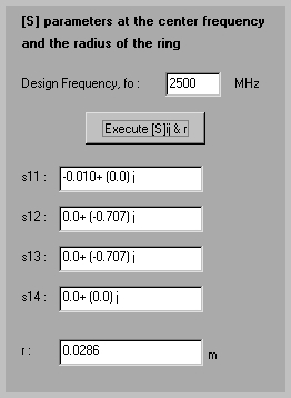
After obtaning S paramaters at center
frequency and the radiusof the ring then you might see the S parameter
magnitudes versus frequency plot on the next page by clicking the Go
to S parameter Anaysis button. On that you will see a panel for the
specification of frequncy axis range and the parameter(s) to be plotted
be plotted. While specifiying the requency axis range be careful not to
enter real Hertz numbers. Here the enter numbers you entered will be taken
as the multiple of center frequency and the plot will be drawn between
those numbers times center frequency fo, e.g between 0.5xfo and and 1.5xfo.
Then choose the S parameter you wish
to be plotted by clicking on the radiobuttons next to each parameter label.
Or you may click on All radiobutton to see the plot of all parameters.
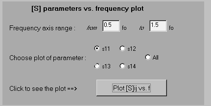
After you made specificications about the frequenxy axis range of the plot and the parameteres to be plotted just click on the Plot [S]ij vs. f button to see the plot. The you will see something like below image. The y axis of the plot is [S]ij in dB scale, i.e logarithmic scale, that is for example in the plot of s11 what you see actually is the plot of 10xlog(|s11|) (|s11| is absolute value of s11). The y axis is ranged between -40 and 0 since S parameters vary between -1 and 1. the extends of x axis is changable for now but y axis not. In the future it might be possible in higher versions of this toolkit.
