MBX Model for Macro Cell
This model proposes path loss formula for urban area by
considering path loss as a result of signal reduction due to free space
wavefront spreading, multiple diffraction past rows of buildings, and building
shadowing it [1]. The geometry for this model is given in following figure 1.
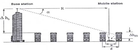
Figure 1. [1 ], geometry for MBX model
This model can be applied to cases when
base station antenna is above, below and near the average rooftop level.
However, in this section, formulas could be applied only case when base station
antenna is above the rooftop levels.
(1)
This
model approaches the problem as Walfisch-Bertoni approaches. It finds that
plane wave multiple diffraction fields reduces to
(2)
![]()
where,
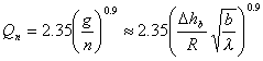
n is number of
buildings, Dhb is base
station antenna height with respect to the average rooftop level, and b is the
separation between buildings as shown in figure 1.
(3)
By using above approximations, and
including free space loss and diffraction from the rooftop to street loss
following formula is derived:
(4)

In this equation,
diffraction loss from rooftop to street Lrts is given by following
formula:
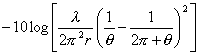
where,
,
in meters
![]()
q=tan-1(Dhm/x) in radians
The comparison of the model with measurements is
given in [1]. The comparison of the model in [1] is done with measurements carried
out by Lee [2]. The obtained figure is given below:
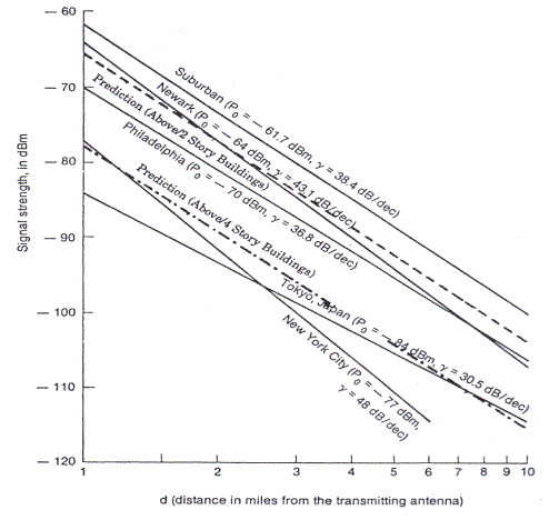
Figure 2 [1]
Comparison of MBX Model with measurements.
This figure shows that predicted curves for suburban
area are lower than the measured value. The predicted signal for urban are
(four story houses) is above the measured level.
The comparison of the model is also done with
Okumura’s measurements. The obtained plot for comparison is given below by
using Wireless Simulator Program given in Figure 3.
In this plot, it is observed that MBX models
correlates with Okumura-Hata results for suburban case. Actually, it is
expected because it is difficult to have terrain type valid for MBX model in
urban and open area. MBX model has 3.3 dB differences for suburban area case,
15 dB for open area and 13.26 dB for urban area case.
Terrain Parameters: Average Width: 73.8 m Average Building Height: 11.25m Percentage of Buildings: 37% Study Parameters: Frequency: 900 MHz, TX Height (hb)=51m Mobile Height (hm)=1.5m TX Gain: 13 dBi City Size: Small/Medium Area Type : Okumura-Hata Path Loss :Suburban Area Okumura-Hata Path Loss (1) : Open Area Okumura-Hata Path Loss (2) : Urban Area
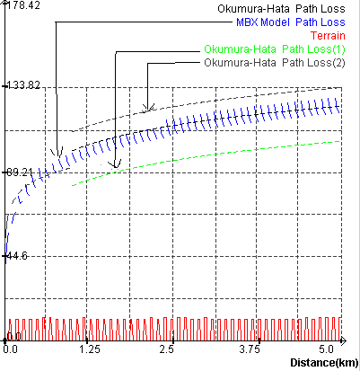
Figure 3 Comparison of MBX model with Okumura Measurements.
The model is valid for 0.3<R<11 km
and frequency 800<f<2000 MHz.
[1] Howard H.Xia, “A simplified Analytical Model for Predicting Path Loss in Urban and Suburban Environments”, IEEE Trans. Veh. Technol. Vol VT-46,No.4, 1997.
[2] W.C.Y.Lee, “ Mobile Cellular Telecommunications
Systems”, New York,McGraw-Hill, 1989