WIRELESS
SIMULATOR PROGRAM (Version 1.0)
1. Definition of the Interface
Elements
1.1
Menu
1.1.1 File Menu
1.1.2 View Menu
1.1.3 Antenna Parameters
Menu
1.1.4 Models Menu
1.2
Models List
1.4
Models Button
1.5
Terrain Button
1.8
Study Button
1.9
Model
Parameters
1.10
Exit Button
2.1.1 How to create your own terrain
2.1.2 How to Paste a terrain
2.1.3 How to save terrain changes
2.1.4 How to see terrains
2.1.5 How to remove a terrain
2.2. How to enter Transmitter
Parameters
2.3. How to enter Receiver Parameters
2.4. How to select study model
2.5. How to enter model Parameters
3. How to learn information about
models
1. Definition of the Interface Elements
In figure 1.1
below, a demonstration of interface elements is given.
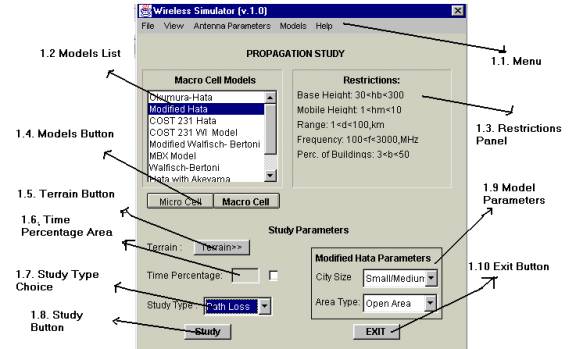
Figure 1.1
Demonstration of Interface Elements
1.1. Menu
This menu contains File, View, Antenna Parameters, Models and Help Menu. Detailed information for each item given below:
1.1.1. File
Menu
As seen in figure 1.1.1.1 below, in file menu, there are two menu items. Menu item Terrain has the same function with Terrain button (see 1.5). Second item Exit has the same function with exit button (see 1.10).
Figure 1.1.1.1. File Menu Item
1.1.2 View Menu
As seen in figure 1.1.2.1 below, view menu has two items, Terrain and Results.
Terrain item is used in order to see the
plot of the terrains. (see 5.) . In the same way,
Results menu item is used to see the plot of the results (see 4).
Figure 1.1.2 View Menu Items
1.1.3 Antenna Parameters Menu
As seen in figure 1.1.3.1, this menu contains two items, Transmitter and Receiver. Transmitter item is used to see the Transmitting antenna parameters (see 2.2), and Receiver item is used to see the Receiving antenna parameters (see 2.3).

Figure 1.1.3.1 Antenna Paremeters Menu Item
1.1.4 Models Menu
As seen in figure 1.1.4.1, this menu contains two sub menu, macro cells and micro cells. Macro cells menu contains macro cell models given in Models list and micro cell menu contains micro cells models. This menu is used to have information about clicked menu item.
Figure 1.1.4.1 Models Menu Item
1.2 Model List
As seen in figure 1.2.1 below, there are two types of model list, macro cell and micro cell. User selects his/her study model by using this list. Macro cell and micro cell models are seen by using models buttons (see 1.4).

Figure 1.2.1 Model List
1.3 Restriction Panel
As seen in figure 1.3.1 below, this panel shows restrictions of the model selected from model list.
Figure 1.4 Restriction Panel
If entered values are not agreed with restrictions of the model, the parameter which is not agreed will be bold.
1.4
Models Button
As seen in figure 1.3.1 , when clicked on buttons, each button gets folded and shows models list in list item.
Figure 1.3.1 Models Button
1.5 Terrain Button
This button is used to call terrain menu explained in Section 2.1 . (see 2.1)
1.6 Time Percentage Area
This area is used to allow user to enter time percentage value. However, it is not available for version 1.0.and will be available for later versions.
1.7 Study Type Choice
As seen in figure 1.7.1, this choice contains path loss and field strength choices. User use this choice list in order to select study type.
Figure 1.7.1 Study Type Choice
1.8 Study Button
This button is used to do a study with given parameters.
1.9 Model Parameters
As seen in figure 1.9.1, each model has each own parameter. When a model is selected from model list, this part changes its parameters with respect to selected model name.
Figure 1.9.1 Model Parameters
1.10 Exit
Button
This button is used to terminate the program.
2.
How to do a Study
In order to do a study , first terrain is loaded, then transmitter and receiver parameters are entered, later, study parameters and model parameters are entered , after all, study button is clicked.
2.1
How to load a terrain
In order to load a terrain, terrain Button in mainframe or terrain menu in file menu are used. When these items are clicked, following figure will appear.
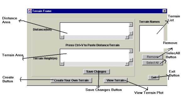
Figure 2.1.1 Terrain Frame
2.1.1. How
to create your own terrain
By using create your own terrain button, a frame shown in figure 2.1.1.1 will appear.
Figure 2.1.1.1 Create your own terrain Frame.
After entering values into text fields, create terrain button is pressed to create a new terrain. In this frame, it should be cared that deviation couldn’t be higher than Average Rooftop level and Average Street width .All fields can accept nonnegative double type values.
2.1.2
How to paste a Terrain
As seen in figure 2.1.1, after pasting distance and terrain information in to distance and terrain area, save changes button should clicked. Then, new terrain item will be added to terrain names list. It should be noted that distance should be in km and terrain should be in meters and also both must be nonnegative number. The information entered in the areas should have space between successive points.
2.1.3
How to save terrain changes
After making changes in the terrains such as removing terrain from terrain list, editing value in text areas, or pasting new terrain into text areas, save changes button should be clicked to make changes updated.
2.1.4
How to see terrains
In order to see terrains, view terrain button is used. Only saved terrains can be seen by using plot program. That means that only terrains shown in terrain list could be available to see.
2.1.5
How to remove a terrain
In order to remove a terrain from terrain list, removed terrain or terrains are selected from remove list and remove button is clicked. In order to make this remove operation valid also save changes button is clicked. After this operation, selected terrain will be removed from both terrain list and memory.
2.2. How
to enter Transmitter Parameters
When transmitter menu item is clicked from Antenna Parameters menu, following figure 2.2.1 will appear.
Figure
2.2.1 Transmitter Frame
Name, coordinate, Antenna Type, Polarization, Base Unit Receiving Sensitivity areas are not available for version 1.0. If study type is field strength, it is obligatory to enter transmitter power. The remaining areas, base station height, frequency and transmitter gain must be filled each time. In addition, it should be noted that base station antenna height is not effective height with respect to ground. It is height of antenna itself. After making changes, Ok button is pressed and then program will terminate by saving given data.
2.3 How to enter Receiver Parameters
By clicking on Receiver menu item from Antenna Parameters Menu , following figure 2.3.1 will appear.
Figure 2.3.1 Receiver Parameters
Maximum ERPd , sensitivity, and RX type areas are not available in version 1.0. If study type is field strength, antenna gain must be given. For path loss study type, it is not necessary. Receiver height must be positive and agree with used model restrictions.
2.4 How to select study model
In order to select study model, models list (see 1.2) is used. Depending on model type such as macro or micro, models list will include different model names. If macro cell model is wanted to be selected, firstly, macro cell button ( See 1.4) is clicked then, desired model is selected from the list. For the micro cell models, the same procedure is followed.
2.5 How to enter model parameters
Some models require different model parameters (see 1.9) given in model parameters panel. By selecting required parameters, this part is done.
3.
How to learn information about models
In order to have information about models used in Wireless Simulator program, models menu (see 1.1.4) is used. After clicking on the desired model, information about the selected model will appear in a web browser.
4.
How to see results
In order to see the results of study, from view menu , results menu are clicked. After clicking on result menu following figure 4.1 will appear. It should be noted that it is impossible to see results before doing a study. Also, to see the results, there shouldn’t be any error such as restriction error during study.
Figure 4.1 Results plot.
Detailed information about plotting part is given in plot help (see Plot Help). It should be known that after doing a study, if terrain didn’t change, result of the study would be automatically on the result screen for selected terrain. Only 7 study results could be seen on the same plot. In order to see more, a new result plot should be opened. Moreover, program will not allow to user to open a new result plot unless terrain changed or seventh study is done.
5.
How to see terrain
In order to see the terrain, from view menu , terrain menu is clicked. After clicking on terrain menu following figure 5.1 will appear.
Figure
5.1 Terrain Plot
It should be noted that up to 1000 terrain could be seen from terrain menu. After doing a study terrain menu will be disabled unless terrain changed. It is possible to see any terrain without doing a study. Detailed information about plot is given in plot help (see plot help).
6.
General information
This program calculates path loss / field strength values with given parameters for given terrain. Results are found only in streets and no calculation are done at building tops. Before using the program, it is suggested that help part should be read at least once.